
![]()
2005-2013
Last updated on
November 27, 2011

VOICES from the Niagara Tunnel - A Living History
(click link above for more information)
Niagara Tunnel Project
LIST OF TUNNEL SUPPORT VEHICLES
Niagara Tunnel Project
Support Vehicles, Carriers & Bridges
in chronological progression
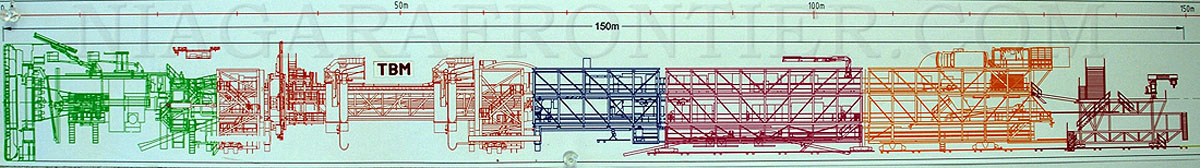
1. TBM & Support 150 meters in length
(TBM alone is 30 meters)
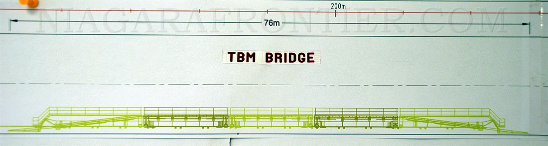
2. TBM Bridge 76 meters in length
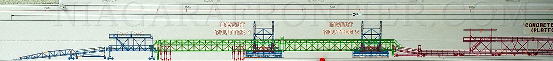
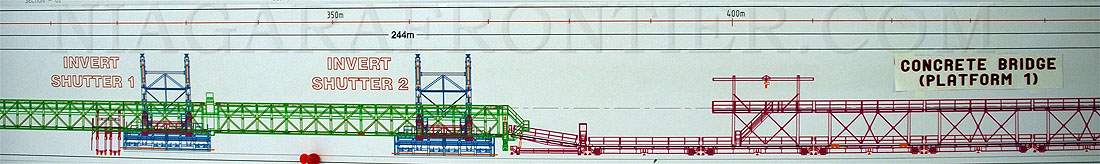
3. Invert Shutter #1
Invert Shutter #2
Concrete Bridge (Platform #1) (110m)
244 meters in length
THE INVERT BRIDGE TRAIN
The Invert Bridge train is pouring finish concrete to the bottom 112° of the tunnel. The train is approximately 244 meters in length and contains two form works consisting of 12.5 meter long bays. Each bay requires 120m3 of concrete. With a crew of 20-21 workers working two shifts, the invert will pour two bays daily. Typically it takes about 7 hours to pour one 12.5 meter long bay. The drying time before the form is moved is 6-7 hours. A double layer of polyolefin (3 millimeters thick) waterproof membrane is being applied to the tunnel invert in advance of the final concrete pouring.
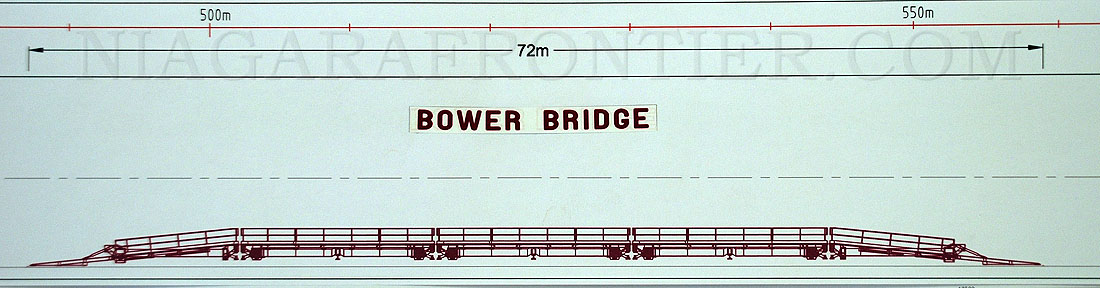
4. Bower Bridge 72 meters in length
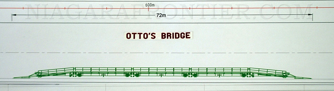
5. Otto’s Bridge 72 meters in length
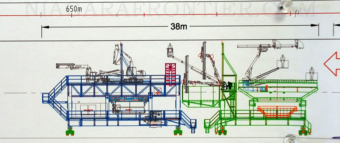
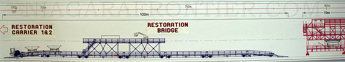
6. Restoration Carrier #1 38 meters in length
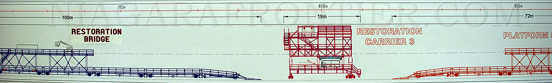
7. Restoration Bridge 100 meters in length
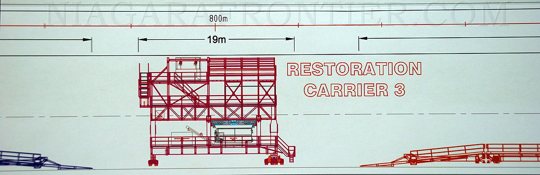
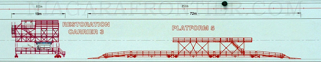
8. Restoration Carrier #3 19 meters in length
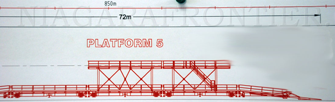
9. Platform 5 72 meters in length
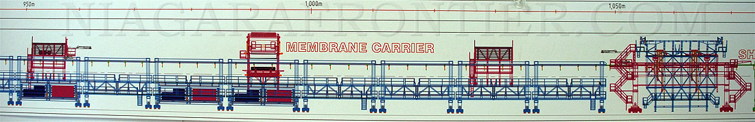
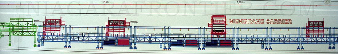
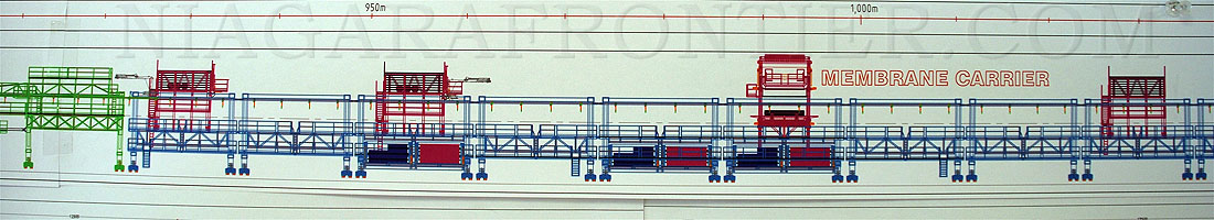
10. Membrane Carrier
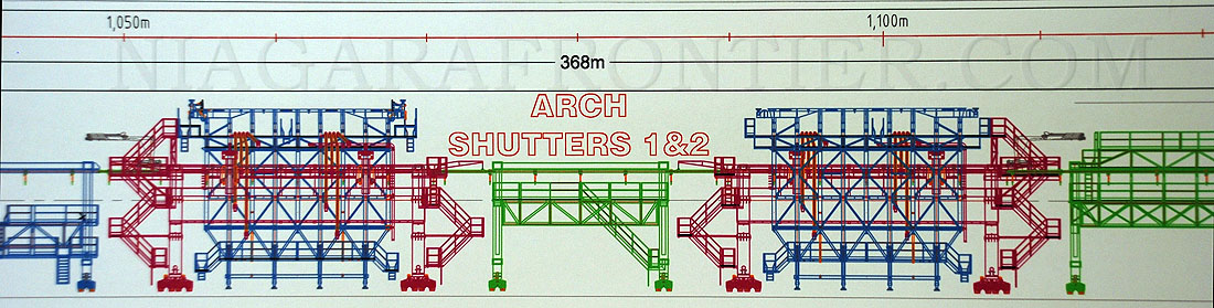
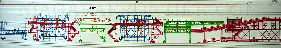
Arch Shutters #1 & #2
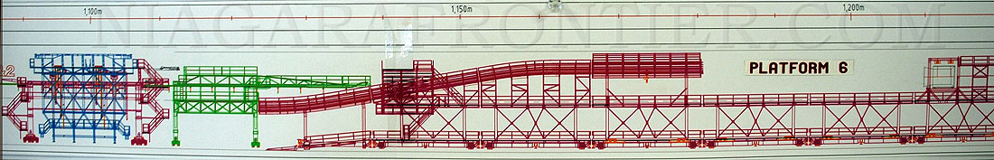
Platform 6 (130m)
368 meters in length
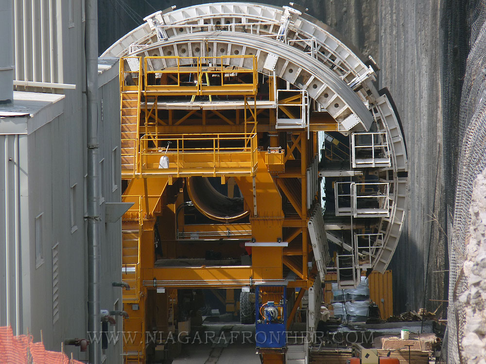
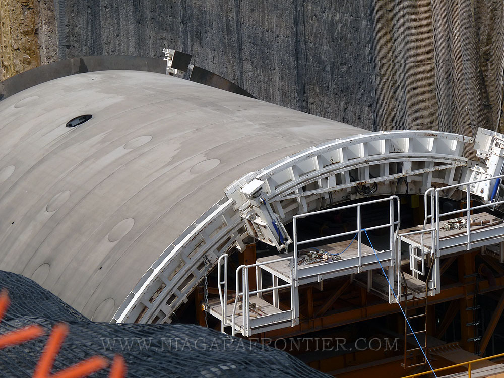
THE ARCH FORMS
A double layer of polyolefin (3 millimeters thick) waterproof membrane is being applied to the tunnel wall in advance of the final concrete pouring. The membrane is attached to the Shotcrete coated wall by use of Velcro. The first arch form is always 2 bay lengths (one already poured and one ready for pouring) ahead of the second arch form. The front arch form pours every other bay, the rear arch form fills the gaps.
The Arch Forms being prepared
The Arch Forms are pouring the finish concrete to upper 248° of the tunnel lining. At the current time one shift is operating daily pouring concrete into a 12.5 meter long bay. The concrete is poured continuously until the bay is filled. The concrete is poured on both sides of the form on an equal basis to ensure the form remains centered. During the pour, selected sections of the arch form vibrates by use of pneumatics. This vibration helps the concrete to settle and compress properly. Moisture is drawn to the form and aids in forming a smooth surface skin. Access portals on the arch form allow workers to aid the distribution and settling of the concrete using handheld vibration tools. Typically it takes about 7 hours to pour one 12.5 meter long bay of the arch form utilizing approximately 240 m3 of concrete. Concrete is pumped through concrete ports built into the arch form. After the concrete is poured the forms of the arch remain in place for 10 hours to allow the concrete to dry. Twenty-two men are employed on the arch form. Currently, concrete is supplied to the forms from the surface via pipeline. This will continue for the initial 500 meters. A support bridge is being prepared to attach to the arch form that will allow concrete to be delivered by vehicles as it progresses further into the tunnel.
There are two Arch Forms in the tunnel. In the near future, both forms will be utilized at the same time resulting in the pouring of a daily maximum limit of 25 meters. The two forms work in tandem following behind a membrane liner. The Arch Form train is 368 meters in length.
The arch forms will pour 3-4 bays per week.
The Shutter Arch Carriers being prepared
The Shutter Arch Concrete Carriers are pouring the finish concrete to to upper 240° of the tunnel lining. At the current time one shift is operating daily pouring concrete into a 12.5 meter long bay. The concrete is poured continuously until the bay is filled. During the pour, the entire arch form vibrates by use of hydraulics. This vibration or "shutter" helps the concrete to settle and compress properly. Access portals on the arch form allow workers to aid the distribution and settling of the concrete using handheld vibration tools. Typically it takes about 7 hours to pour one 12.5 meter long bay of the arch form utilizing approximately 240 m3 of concrete. Concrete is injected through concrete nozzle ports built into the shutter form. After the concrete is poured the forms of the arch remain in place for 10 hours to allow the concrete to dry. Twenty-two men are employed on the shutter arch carrier. Currently, concrete is supplied to the carrier from the surface via pipeline. This will continue for the initial 500 meters. A support bridge is being prepared to attach to the Shutter Arch train that will allow concrete to be delivered by a vehicle as it progresses further into the tunnel.
There are two Shutter Arch Concrete Carriers in the tunnel. In the near future, both carriers will be utilized at the same time resulting in the pouring of a daily maximum limit of 25 meters. The two carriers work in tandem following behind a membrane liner carrier. The Shutter Arch train is 368 meters in length.
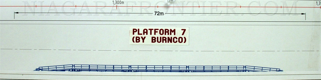
11. Platform 7 (by Burnco) 72 meters
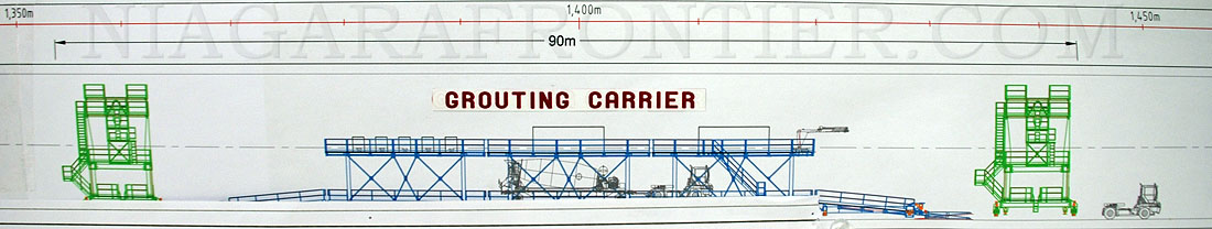
12. Grout Carrier 90 meters
GROUTING
There will be two different types of grouting:
1. the contact grouting to make sure that the inner lining concrete is properly bedded, and
2. the pre-stress grouting to compensate for shrinkage and creeping of the inner lining concrete. Basically this is an substitute for reinforcement.
Total Length of the TBM, support vehicles, carriers & bridges if placed end to end would be 1,450 meters in length.
| NIAGARA FALLS THUNDER ALLEY NAVIGATOR | ||
| SITE MAP | ||
THANK YOU FOR VISITING THE
STRABAG INC.